Makita Battery Hacking - Part 2
It's been almost 3 years since I posted the first part of this project. After getting the firmware from the battery I soon realised that the reset procedure for these batteries are not very obvious. At the time of writing this I still don't have the full solution for these older batteries, but I am close. This year I was contacted by Romain, looking to solve the same issue. He donated two newer boards with newer microcontrollers to me. One of these boards were based on an STM32 microcontroller and luckily for us, the read protection had not been set! So about 5 minutes after receiving the boards we were in business reverse engineering the binary in Ghidra.
We soon discovered that there were many additional functions in these newer batteries, the only part that was similar was the battery-charger commands that have to remain the same for backwards compatibility. Making sense of a dissasembled binary is very time consuming work and I spent many long nights on this project going through commands one by one.
After a few days I had figured out where the error code was stored in EEPROM and where it later was loaded in RAM. Looking through all the pointers to this address I finally found a command that does what we wanted! It passed this memory adress to a memset function, setting all error messages to 0, great! Studying this command even more revealed that there were some additonal checks that had to be met before it was possible to access this command. Following all these conditions and the values I found out that there were a few commands that needed to be sent before we had access to this command. One of these was a command that expected a two byte input, this was later compared with a static value and set the a few RAM values that was needed in order to use the other command. We had the solution!
STM32
Reverse engineering a microcontroller with debugging capabilities certainly helps! Using STM32CubeIDE it is possible to create a launcher for the elf file and then start the debugger. Then we can add breakpoints and step into instructions!
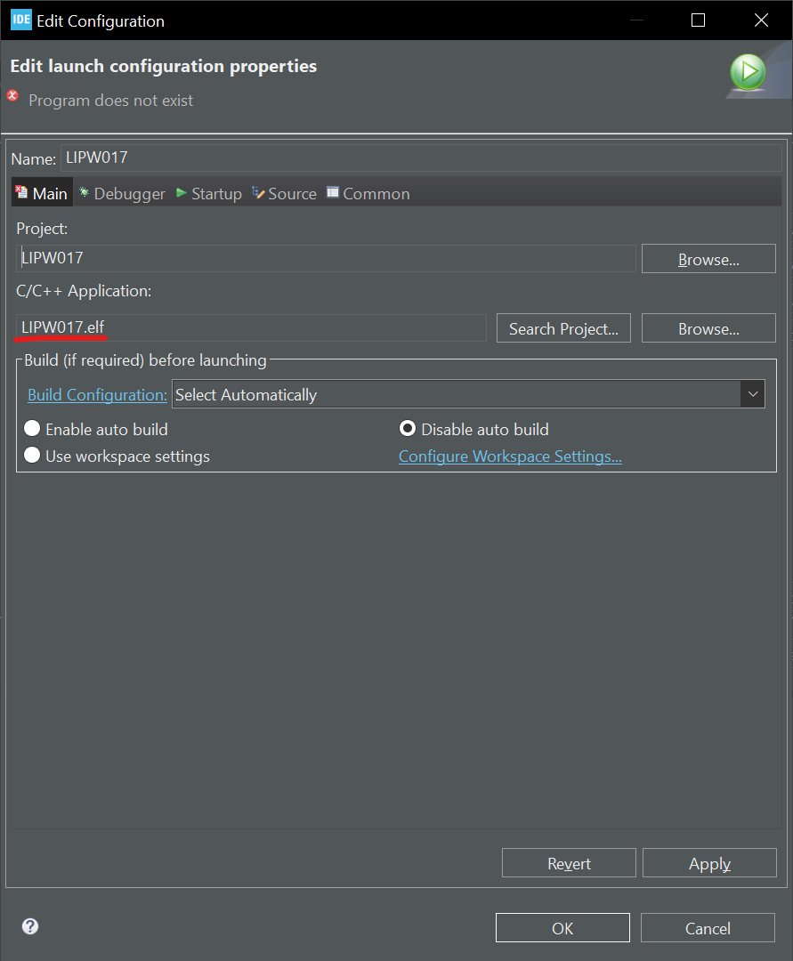 Launch settings.
It's important to also enable the option to suspend the watchdog during breaks.
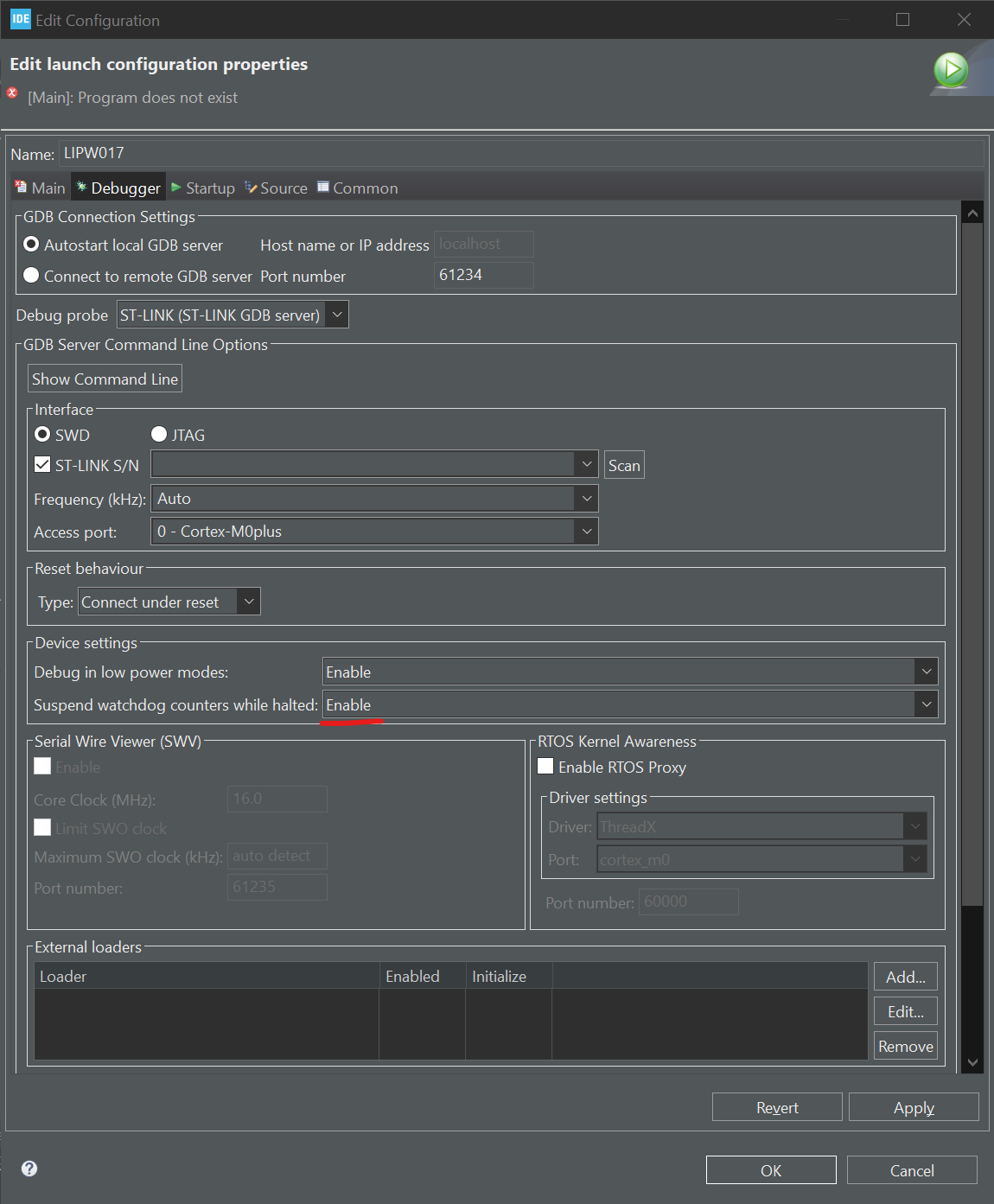 Debugger settings.
Makita protocol
The protocol they use is based on Maxims OneWire protocol, the reset procedure (start of communication), skip ROM and read ROM functions are implemented. The timing differs from the standard, possibly to obfuscate the communication. I will release all findings on Github once I have had the time to document everything and cleaned up the code.
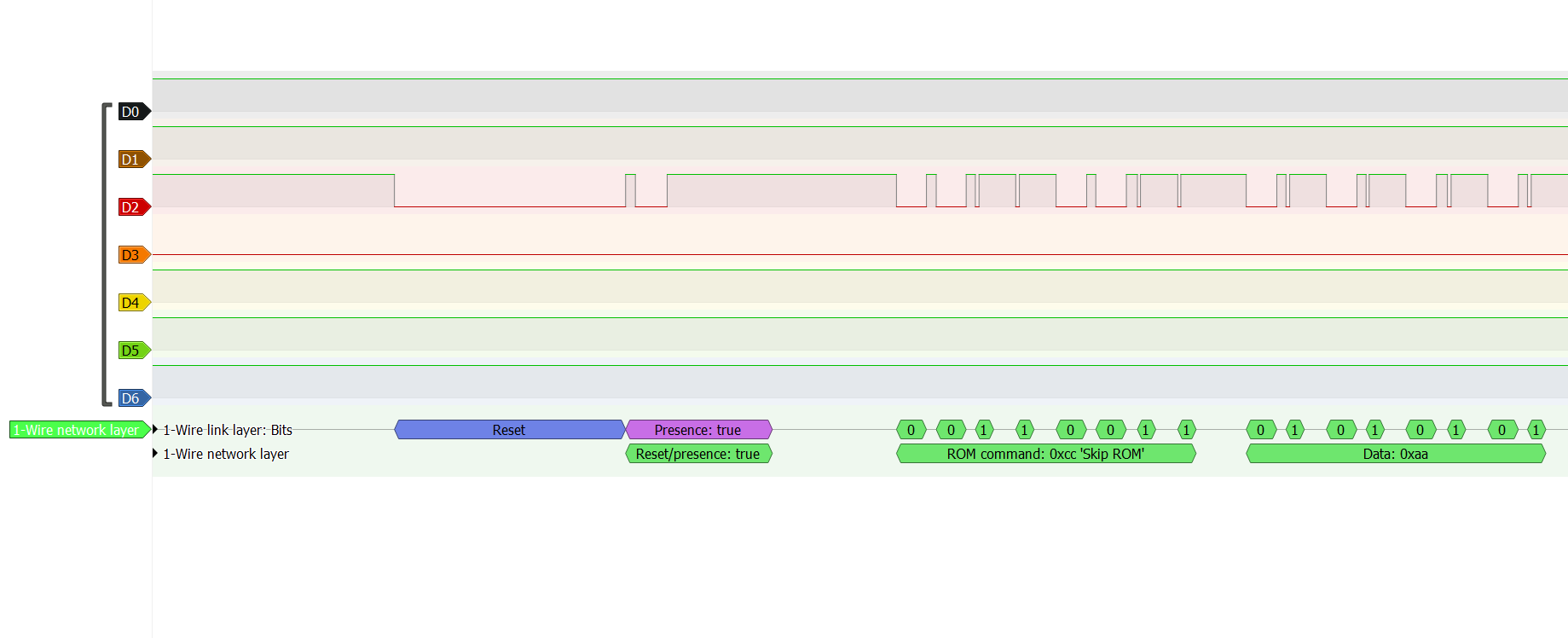 Pulseview capture.
From the F0513 variant I dumped previously, I had documented each command and what they do. The list is still incomplete and additionally the most important part is missing. We have found a non-standard command that goes to a backdoor that switches protocol to single wire UART communication. Through this backdoor it seems that it is possible to read the whole firmware and also write to memory! Neat! More on this in another post.
Standard commands are:
- 0xCC - Skip ROM, expects next command.
- 0x33 - Read ROM, outputs ROM ID, 8 bytes.
Second command bytes:
- 0xF0 - Next byte: 00 = Output battery message provided that some conditions are met.
- 0X0F - Next byte: 16 = Input 10 bytes to battery message buffer. 00 = Input 32 bytes to battery message buffer.
- 0xAA - Next byte: 00 = Output battery message without any conditions.
- 0x55 - Next byte: A5 = Trigger write to flash
- 0xD1 - Output 3x battery messages.
- 0x99 - Temporary access to second command tree.
- 0x10 - Next byte: 21 = Force entry to second command panel. Overwrites first byte of ROM ID. This will make default entry to second command tree.
- 0x31-0x35 - output 2 bytes, cell voltages.
- 0x52 - output 2 bytes, temperature
Second command tree:
- 0x65 - Call sub_2E68. Then output from byte_FD72
- 0x74 - Call sub_2EC9 . Then output byte_FDD2 and byte_FDD3.
- 0x16 - Set byte_FED5 = 0x00, byte_FED4 = 0x0A, word_FE8C = 0x00, set bit byte_FE9B.02h
- 0x01 - Output 1 byte. 0x01.
- 0x35 - Next 1 byte, write to CR51.
- 0x53 - Output 10 bytes from FD8E.
- 0x62 - Output 2 bytes. byte_FD7E and byte_FD7F
- 0x33 - Output ROM ID (Starting at byte_FD58)
- 0x34 - Output second ROM ID (Starting at byte_FD68)
- 0x4B - Next 8 bytes write to ROM ID (Starting at byte_FD58)
- 0x4C - Next 8 bytes write to second ROM ID (Starting at byte_FD68)
- 0xA1 - Output 1 byte. byte_FD63
- 0x31 - Output 2 bytes. 0x30 and 0x18. Battery model.
- 0x32 - Output 2 bytes. 0x01 and 0x01. Battery firmware.
- 0x64 - Output 10 bytes from byte_FD72.
- 0x73 - Output 2 bytes. byte_FDD2 and byte_FDD3
- 0xE3 - Output 1 byte. byte_FE5B
- 0xCC - Next byte: D1 = Same as main panel. 99 = Same as main panel without setting byte_FE9B.04h.
- 0x11 - Massive reset. TBD
- 0x36 - Calls sub_2DD6. TBD
- 0x45 -
- 0x46 - Calls sub_2DC1. TBD
- 0x42 - Writes to flash register 03 if some conditions are met. TBD
- 0x51 - Writes to flash register 0D if FDD3 is with 0x56-0x3A
- 0x71 - Clears PM6.PM61
- 0x82 - Sets PM6.PM61
- 0x84 - Sets PM7.PM75
- 0x95 - Clears PM7.PM75
- 0x94 - Sets bit 2 in P7. Sets fuse trigger, will release smoke.
- 0xB6 - Clears bit 2 in P7. Clears fuse trigger
- 0xB2 - Clears bit 0 in P7
- 0xC1 - Sets bit 0 in P7
- 0xE1 -
- 0xE2 -
6000h Flash section Flash messages have a header before stored data.
Headers:
- 0x01 - ROM ID, RAM = FD58-FD60
- 0x02 - RAM = FD78-FD79
- 0x03 - RAM = FD8E-FD8F, FD9E-FD9F, FDAE-FDAF, FDBE-FDBF, FDCE-FDCF
- 0x04 - Some error counter, RAM = FD7A, Limit 04
- 0x05 - Some error counter, RAM = FD7C, Limit 03
- 0x06 - RAM = FD7B
- 0x07 - Some error counter, RAM = FD7D, Limit 02
- 0x08 - RAM = FD88
- 0x09 - RAM = FD89
- 0x0A - ROM ID2, RAM = FD68-FD70
- 0x0B - RAM = FD8A, Limit = 03
- 0x0C - Fuse was blown by software, RAM = FD8B, Limit = 01
- 0x0D -
- 0x0E - RAM = FD8C, Limit = 02
Programmer
Since the timing was very critical, off-the-shelf programmers/tools won't work very well, so we opted to use an Arduino Uno as a USB to OneWire interface. In the future I would also like to explore the option to add additonal support for EV2300/EV2400 since this tool is very common in the battery repair industry.
 ArduinoOBI Interface schematic.
Open Battery Information
As mentioned I will release this project on Github. I've created a repository called Open Battery Information, the idea is to create a repair tool and manual for repairing not only Makita batteries but all kinds of batteries.
I plan to release the diagnostic tool OBI-1 and the Arduino Interface to start with.
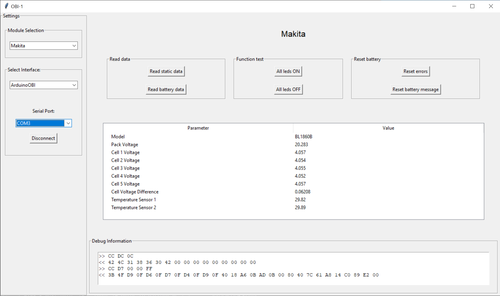 OBI-1.
I'm relying on the community to step in here and contribute. As people in the battery industry knows, information like this is very valuable and releasing everything for free was not the easiest decision to make but I feel like it is the right one. By releasing it open for everyone, more batteries can be repaired and will lead to less electronic waste. If you appreciate what I try to do here and would like to support this cause, I would very much appreciate any contributions! I have also set up Github Sponsors for this purpose.
A big thanks to Romain for all the help with reverse engineering, motivation and the donor boards!